2026.06.19
 News
News
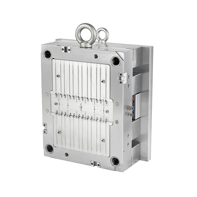
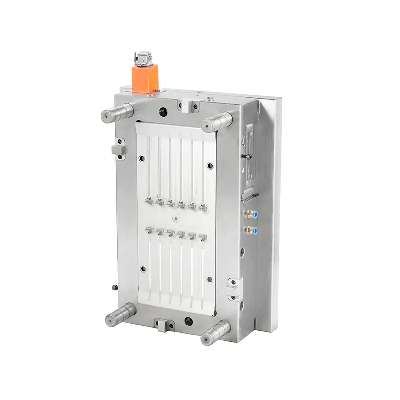
Automotive electrical systems depend on precise signal transmission, and even a minor deviation in connector geometry can affect entire harness performance. An Automotive Connector Mold must maintain extremely tight tolerances because modern connectors often include multiple cavities, micro-pin housings, and complex locking structures. Misalignment of pins is one of the most frequently discussed issues in injection molding troubleshooting for automotive-grade components, especially with high-temperature engineering plastics such as PBT, PA66, and LCP.
Industry analysis and molding defect reports indicate that pin misalignment is rarely caused by a single factor. It usually emerges from the combined effects of tooling precision loss, uneven flow behavior, and structural stress within multi-cavity systems.
Automotive connectors often contain multiple pin positions arranged in compact geometries. During injection, molten resin does not always distribute evenly across all cavities.
Common flow-related behaviors include:
This imbalance can shift internal core alignment during packing pressure stages. Even slight pressure differences may result in micro-deformation of pin sleeves, which becomes visible during assembly testing.
Multi-cavity imbalance is often amplified in high-speed injection cycles, where filling time is shortened to improve productivity.
Core pins inside connector molds are extremely slender and often extend deep into cavity structures. Under repeated high-pressure injection, these pins can experience gradual deflection.
Observed mechanical behaviors include:
Even deformation measured in microns can translate into visible misalignment in assembled connectors. In high-density pin arrays, this effect compounds across multiple channels, increasing the likelihood of connector mismatch during mating tests.
Connector molds operate under cyclical heating conditions, often with mold temperatures ranging from 70°C to over 120°C depending on resin type. Core inserts, cavity blocks, and guide components expand at different rates.
Typical thermal mismatch effects include:
Over time, repeated expansion and contraction cycles create micro-clearance changes. These changes may not be visible during routine inspection but directly affect pin positioning accuracy during production runs.
Connector molds rely heavily on gate placement and runner design to ensure balanced flow into each cavity. Poorly optimized gating systems can introduce directional stress into the mold structure.
Common gating issues include:
Such conditions can distort delicate pin geometries during the packing phase. Once deformation begins at the entry region, it often propagates toward the inner cavity structure, affecting alignment consistency across the entire connector body.
Automotive connectors frequently feature deep internal cavities that require multi-stage ejection systems. Uneven ejection force distribution is a key contributor to pin misalignment.
Mechanical effects include:
Repeated uneven ejection gradually impacts cavity surface integrity. Over time, this can shift alignment reference points inside the mold, especially in high-cycle production environments.
Connector molds typically process engineering-grade polymers with varying shrinkage rates. Materials such as PA66 or PBT may exhibit anisotropic shrinkage depending on fiber reinforcement direction.
Key shrinkage-related behaviors include:
These variations can subtly reposition internal pin cavities after ejection. While each part may remain within general dimensional tolerance, cumulative variation increases misalignment risk during mating assembly.
Connector molds depend on precision guide pins and bushings to maintain alignment between core and cavity halves. Continuous high-cycle operation introduces gradual wear.
Common wear indicators include:
Once guide systems lose tight tolerance control, even minor mechanical play can translate into measurable pin misalignment at the product level.
Not all misalignment issues originate from mold structure itself. Process variations often mimic tooling defects.
Typical process-related contributors include:
These factors may cause temporary misalignment symptoms that resemble mold wear. Differentiating between process drift and mechanical degradation is essential for avoiding unnecessary mold modification.
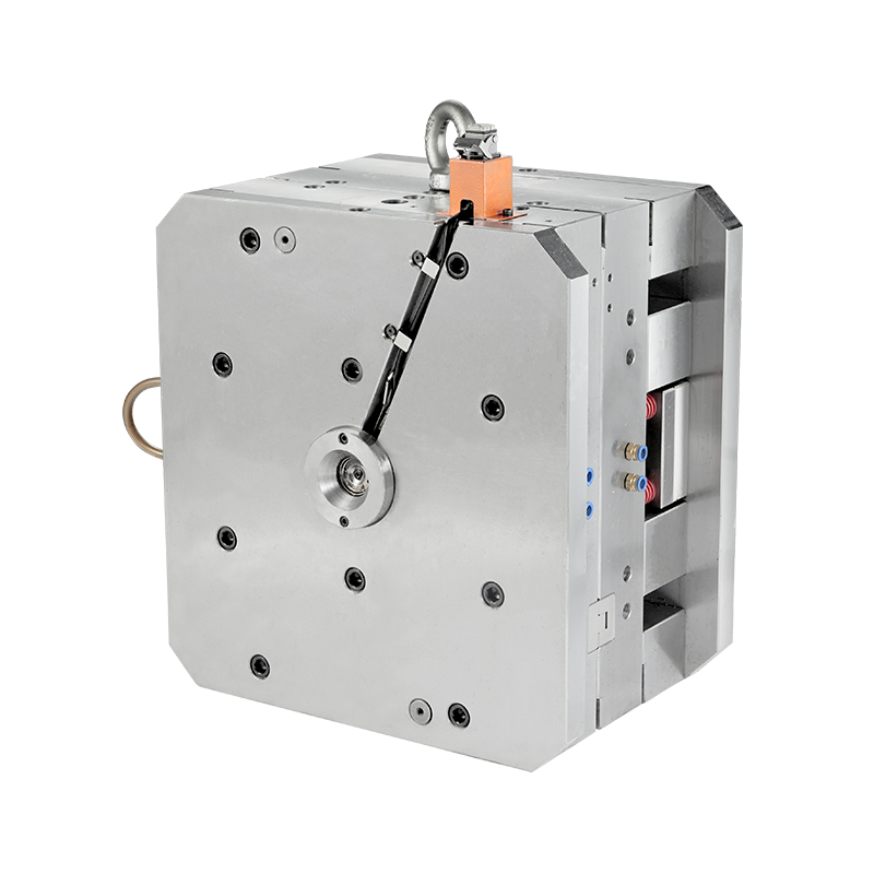
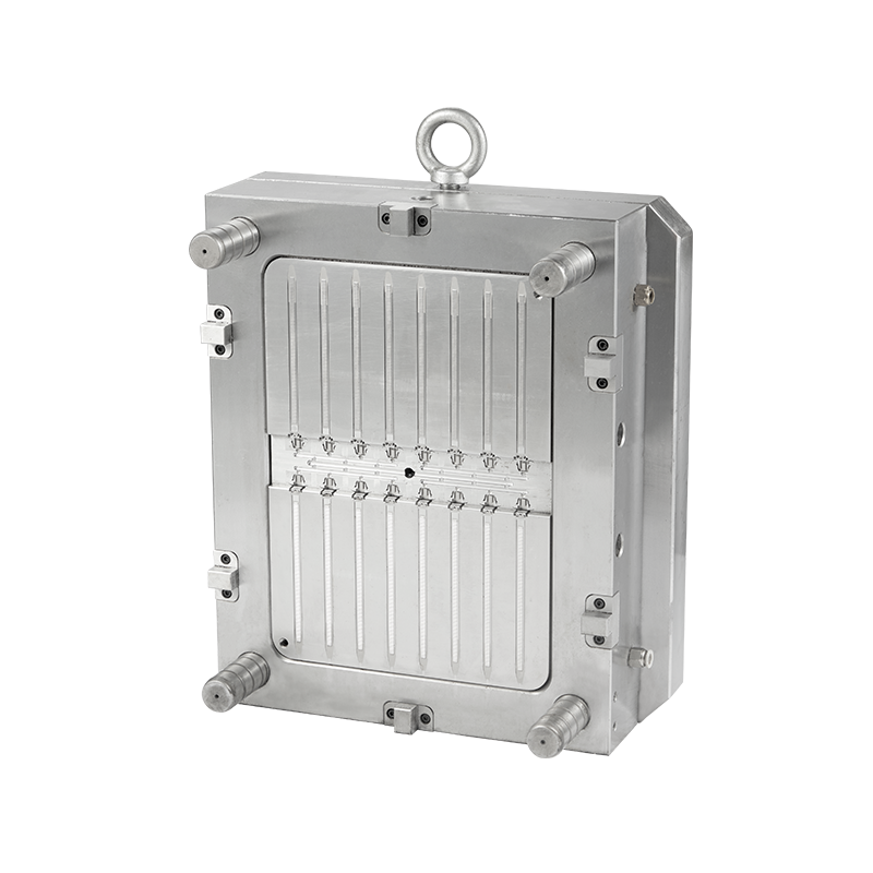
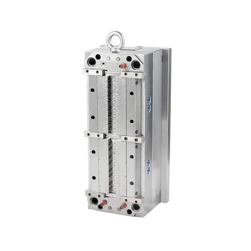
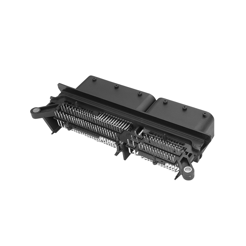
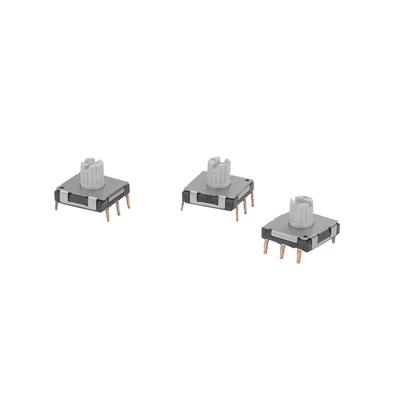
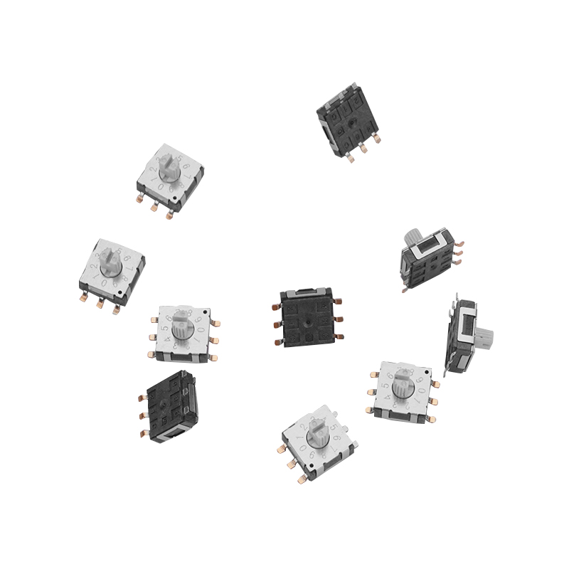
Recommended Products


 English
 中文简体
中文简体 русский