2026.09.18
 News
News
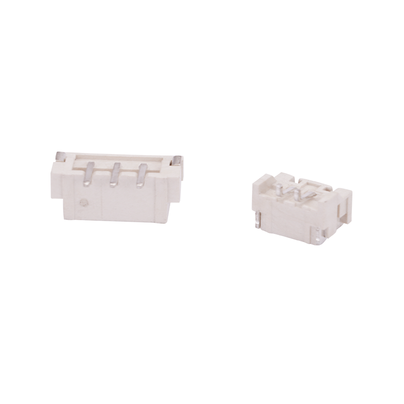
Automotive connectors are compact components, but their plastic housings contain highly sensitive features. Terminal cavities, pin holes, locking structures, sealing surfaces, and thin separating walls must work together within limited dimensional ranges. A deviation that appears insignificant on a general plastic component can become a serious issue in an automotive connector.
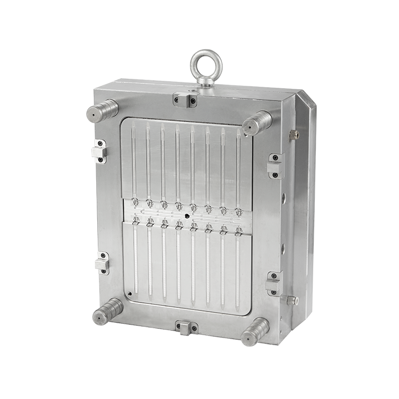
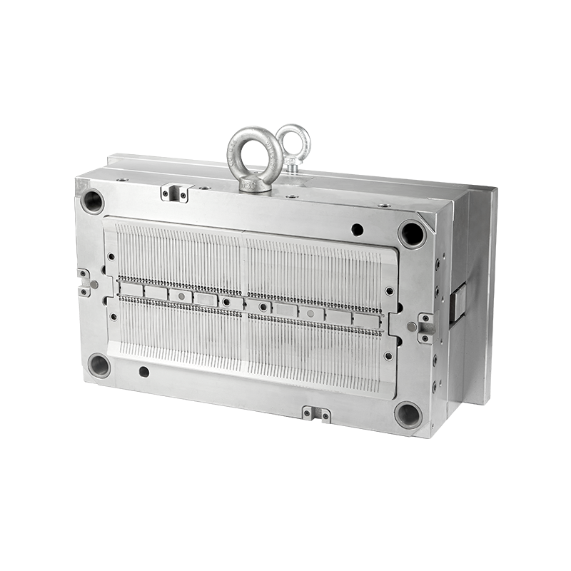
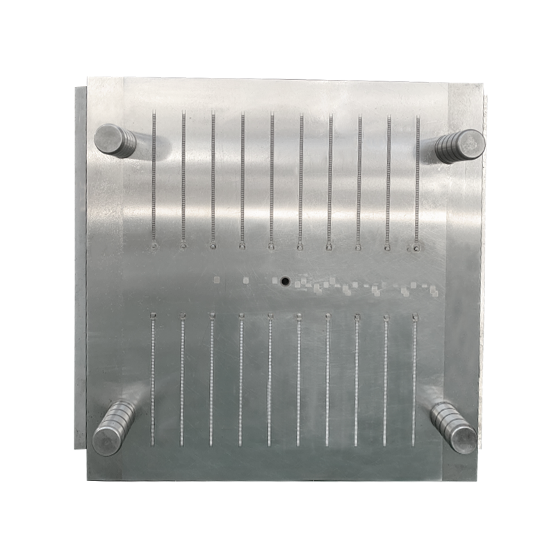
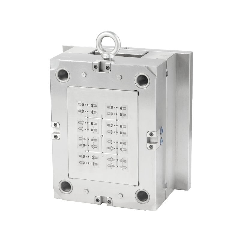
This makes the Precision Automotive Connector Injection Mold fundamentally different from tooling used for larger and less intricate plastic parts. Mold accuracy is closely connected with terminal positioning, connector assembly, and the functional dimensions of the finished housing.
Connector miniaturization continues to compress the available space around terminal cavities. Technical references describe automotive connector designs with wall thicknesses around 0.5 mm and pin holes or pitches close to 0.64 mm. Such dimensions leave limited room for accumulated manufacturing deviations.
| Connector Feature | Typical Design Concern | Possible Result of Deviation |
| Terminal cavity | Position and size | Terminal insertion difficulty |
| Pin hole | Pitch and alignment | Mating problems |
| Divider wall | Thin-wall accuracy | Weak or damaged structure |
| Locking feature | Snap-fit dimensions | Unstable retention |
| Sealing area | Surface and profile accuracy | Potential sealing problems |
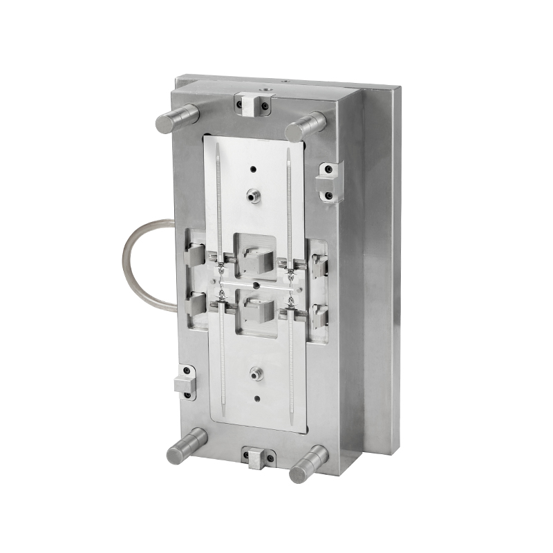
Metal terminals must occupy defined positions inside the plastic housing. During molding, injection pressure can act on inserts, while mold alignment and positioning components determine how accurately the cavity forms around them.
Recent connector mold analysis highlights that even a few hundred microns of insert movement can affect dimensional inspection and final assembly. Mold insert positioning, locating structures, and support around thin terminals therefore deserve attention during tool development.
Connector housings often use narrow walls between terminal cavities. These sections must fill properly without creating excessive deformation, short shots, or flash.
A published automotive connector mold design describes an average wall thickness of approximately 0.5 mm, while modern precision connector applications can involve even smaller features.
Thin sections also change the relationship between material flow and cooling. Uneven wall thickness can produce different shrinkage behavior, which may alter the position of critical connector features.
A connector does not rely on a single dimension. Its final function depends on multiple dimensions working together.
Consider a simplified terminal path:
Terminal position → cavity width → pin spacing → housing wall → mating interface
A small deviation at each stage may accumulate into a noticeable positional difference. Precision connector molding references commonly place critical features within approximately ±0.005–0.05 mm, depending on the component and tolerance requirement.
This is why a Precision Automotive Connector Injection Mold needs tolerance planning at the mold-design stage rather than relying only on final dimensional inspection.
Flash around terminal cavities, parting lines, or insert interfaces may appear as a thin excess layer of plastic. On an ordinary housing, it may be mainly a cosmetic concern. On an automotive connector, it can interfere with terminal insertion, locking, or sealing.
Precision connector molding sources identify flash control as a critical concern for thin-wall engineering plastics, particularly around small shut-off surfaces and micro features.
Automotive connector housings can use engineering plastics such as PBT, PA66, LCP, PPS, and other high-performance materials. Their processing temperatures, viscosity, shrinkage behavior, and reinforcement characteristics can differ considerably.
| Material | Relevant Mold Consideration |
| PBT | Dimensional stability and shrinkage control |
| PA66 | Moisture and shrinkage considerations |
| LCP | High-flow behavior and thin-wall filling |
| PPS | High-temperature processing and wear considerations |
Material selection can therefore influence gate location, cooling strategy, cavity dimensions, and the tolerance that can realistically be maintained. Precision molding guidance specifically identifies resin selection and gate placement as major factors affecting connector dimensional accuracy.
Not every surface on an automotive connector requires the same tolerance level. Inspection should focus on functional dimensions that directly affect assembly and electrical performance.
Some precision connector tooling references report machining tolerances around ±0.002 mm for specialized micro-features, while actual finished-part tolerances depend on material, geometry, molding conditions, and the product specification.
Creating a Precision Automotive Connector Injection Mold is not simply a matter of machining steel to a small tolerance. The product drawing, terminal dimensions, material shrinkage, parting strategy, gate position, insert positioning, and tolerance stack-up all need to be considered together.
Design-for-manufacturing analysis can also identify potential problems with wall thickness, weld lines, warpage, and differential shrinkage before mold components are manufactured.
Automotive connector molds demonstrate how a very small dimensional deviation can have a much larger functional consequence. Terminal alignment, pin spacing, locking structures, thin walls, and sealing interfaces all depend on controlled geometry.
The value of a Precision Automotive Connector Injection Mold therefore lies not simply in achieving small machining numbers. It comes from coordinating mold structure, material behavior, insert positioning, and critical product tolerances so that the finished connector can meet its intended assembly and performance requirements.
Recommended Products



 English
 中文简体
中文简体 русский