2026.09.25
 News
News
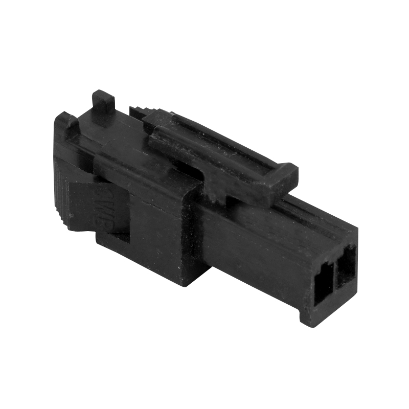
Automotive connectors are rarely simple boxes. A single plastic housing may contain terminal cavities, locking arms, keying slots, ribs, mounting features, sealing surfaces, and narrow internal passages. These details determine how the finished connector mates and locks, but they also place clear limits on the mold structure.
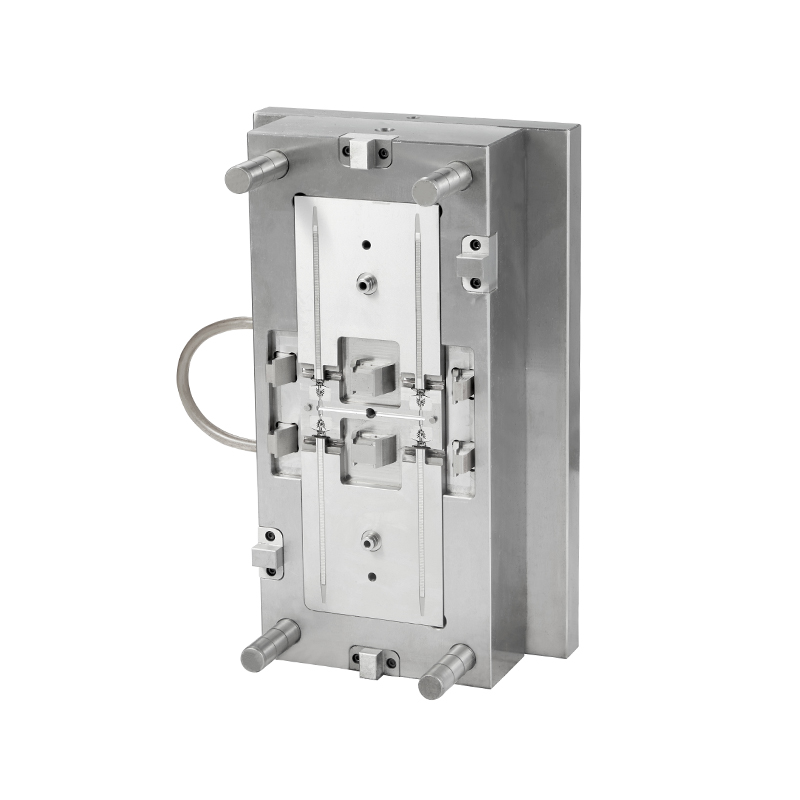
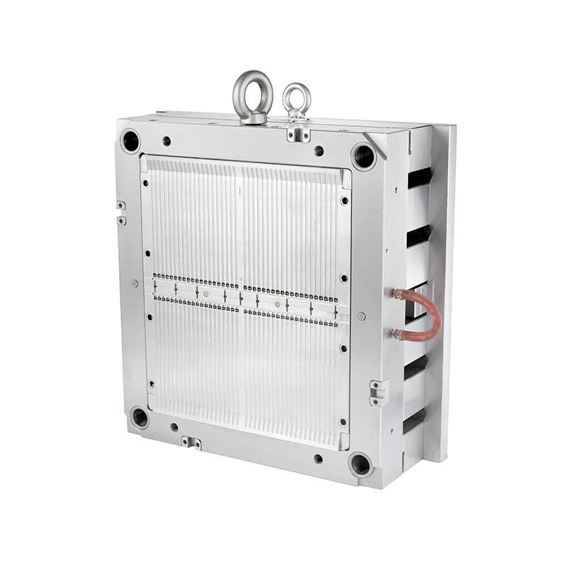
This relationship makes Auto Connector Plastic Injection Mould design a geometry-driven task. The question is not simply how to reproduce the connector shape. The mold also needs to open, fill, cool, and release the part without damaging functional features.
Undercuts are among the clearest examples of product geometry affecting tooling. A connector may require side locks, retaining hooks, lateral grooves, or keying structures that cannot be formed by a simple vertical mold opening.
Connector mold references specifically identify latches, locking mechanisms, and anti-mating structures as features that can require slides or lifters. Simplifying these features during product development can therefore have a direct effect on tooling complexity.
Draft normally helps a molded part separate from the core. Connector housings, however, often contain terminal holes and mating surfaces where dimensional accuracy is more important than generous draft.
| Geometry | Mold Challenge | Design Consideration |
| Outer housing wall | Easy release | Provide suitable draft |
| Deep terminal cavity | Core retention | Balance draft with dimensional requirements |
| Locking surface | Possible interference | Control draft direction carefully |
| Textured area | Higher ejection resistance | Additional draft may be required |
Some connector design references describe draft angles as small as about 0.25° around precision terminal-hole areas, while general external surfaces may use approximately 0.5°–1° or more depending on the geometry and finish.
Such a small angle can make mold polishing and ejection considerably more sensitive to dimensional errors.
Modern connectors often need smaller housings with higher terminal density. This can create narrow walls between adjacent cavities.
A published connector housing example describes dimensional requirements involving small width and height relative to housing length. Such elongated geometry can create warpage concerns after injection molding and even after later thermal exposure.
Thin sections also influence gate placement. A gate positioned too far from a narrow feature may produce difficult filling conditions, while an unsuitable flow direction can increase weld-line or air-trap concerns.
Terminal cavities can be relatively deep compared with the surrounding housing. Their geometry affects core strength, polishing access, cooling, and ejection.
Connector housings may contain multiple terminal cavities within a compact footprint, making the relationship between cavity spacing and mold steel thickness particularly important.
The parting line determines how the two primary mold halves separate. A poor location can place a witness line across a sealing or mating surface, while a carefully planned location can simplify the mold and protect functional areas.
Product geometry should therefore be reviewed together with the proposed opening direction.
General injection-molding guidance also emphasizes that parting-line planning can reduce unnecessary side actions and help determine the appropriate draft direction.
Connector geometry does not leave unlimited freedom for gate placement. Terminal cavities, sealing surfaces, visible areas, and thin walls can all restrict where molten resin should enter.
A connector housing patent provides an interesting example: instead of placing both gates at one end of an elongated housing, its proposed design uses two gates on opposite sides near the middle of the housing length. The approach is intended to improve dimensional integrity for small, elongated connector housings.
| Product Geometry | Potential Gate Concern |
| Long housing | Uneven filling along the length |
| Dense terminal area | Limited gate space |
| Thin wall | Higher filling resistance |
| Visible surface | Gate mark location |
| Sealing surface | Weld line and dimensional integrity |
The same connector geometry can behave differently with different engineering plastics. PBT, PA66, LCP, PPS, and reinforced grades have different flow and shrinkage characteristics.
Automotive connector housings commonly use materials such as PBT, nylon, and other engineering plastics. PBT is frequently used in automotive connector housings because of its mechanical, electrical, heat, and water-related properties.
Glass-fiber reinforcement adds another consideration. Fiber orientation can create directional shrinkage and influence warpage, making gate position and flow direction relevant to the final connector geometry.
Yes. Small changes to connector geometry can sometimes simplify the Auto Connector Plastic Injection Mould without changing the connector's primary function.
DFM analysis can identify conflicts between product geometry and mold construction before steel machining begins. Automotive connector molding case studies also emphasize uniform wall thickness, suitable radii, simulation, and mold engineering as part of the design process.
Connector geometry can place significant limits on injection mould design. A latch may require a side action, a deep terminal cavity may restrict core dimensions, a thin wall may influence gate placement, and an elongated housing may require a different filling strategy.
The design of an Auto Connector Plastic Injection Mould therefore works best when product geometry and mold architecture are developed together. Small changes to draft, wall thickness, undercuts, radii, or gate locations can affect the tooling structure as well as the performance of the finished connector.
For automotive connectors, the mold is not simply a tool that copies the product. Its structure is shaped by the functional geometry of the connector itself.
Recommended Products



 English
 中文简体
中文简体 русский