2026.04.03
 News
News
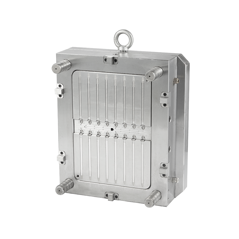
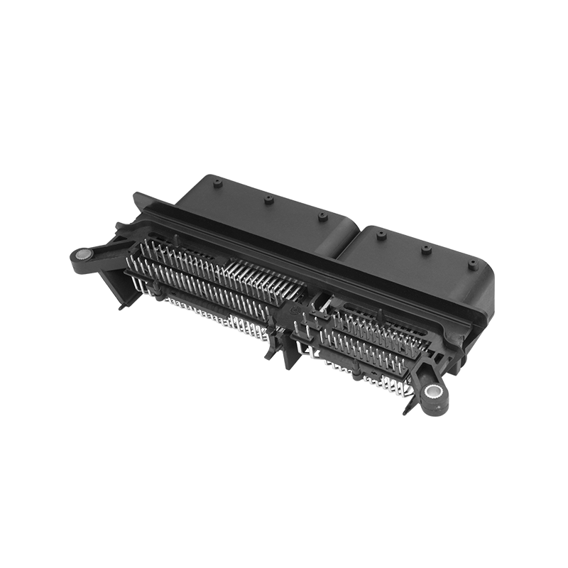
The complexity of an auto connector mold stems directly from the functional requirements of the connector itself. Unlike a simple plastic part, an automotive connector must house metal terminals with extreme precision, maintain a reliable seal against moisture, and often incorporate mechanical locking features—all within a very small space. This translates into mold design requirements that push the boundaries of conventional injection molding.
High Cavitation and Precision: To be economically viable, connector molds are often designed with a high number of cavities—sometimes 16, 32, 64, or even more—to produce many parts in a single cycle. Maintaining identical, precise dimensions across every cavity requires exceptional mold manufacturing accuracy and sophisticated hot runner systems to ensure each cavity fills with molten plastic at the same pressure and temperature.
Complex Internal Mechanisms: Connectors typically feature undercuts—features that prevent the part from being ejected straight out of the mold. These include side holes for terminal locking lances, internal latches for connector position assurance (CPA) devices, and sealing grooves for gaskets. To form these features, the mold must incorporate moving components such as slides, lifters, and collapsible cores that actuate in precise sequence during the opening and ejection phases.
Tight Tolerances: The critical interfaces in a connector—the cavities that hold the terminals—require tolerances measured in microns. If these cavities are too large, the terminal will not be retained securely. If they are too small, the terminal cannot be inserted during assembly. The mold must be capable of producing these features consistently across thousands of production hours.
Material Considerations: Automotive connectors are typically molded from engineering plastics like PBT (polybutylene terephthalate) or PA (polyamide, or nylon), often with glass fiber reinforcement. These materials are abrasive and require molds built from very hard, wear-resistant tool steels. The flow characteristics of these materials also demand careful gate design to avoid weld lines or incomplete fill in thin-wall sections.
Producing defect-free connectors is challenging due to the small size, complex geometry, and tight tolerances involved. Several defects occur with some frequency, and understanding their root causes is essential for effective process control.
Short Shots (Incomplete Fill): This defect occurs when the molten plastic does not fill the mold cavity, resulting in a partially formed part. Common causes include insufficient injection pressure or speed, a restricted gate or runner (often due to a buildup of material or contamination), or material that is too viscous because the melt temperature is too low. In multi-cavity molds, a short shot in only one cavity typically points to a blockage in that specific branch of the runner system.
Flash: Flash is the thin, excess plastic that seeps out of the mold cavity at the parting line or around ejector pins. It occurs when the mold halves do not close completely, allowing material to escape. This can be caused by insufficient clamping force to keep the mold closed against the injection pressure, by contamination or damage on the mold faces preventing proper shut-off, or by injection pressure that is too high. In glass-filled materials, abrasive wear over time can also erode the mold steel at the parting line, creating a path for flash.
Weld Lines: Weld lines (or knit lines) form when two flow fronts of molten plastic meet inside the cavity and do not fully bond. In a connector, this often happens around holes or core pins. A visible weld line is also a potential structural weakness. Causes include low melt or mold temperatures, slow injection speeds that allow the fronts to cool before meeting, or part geometry that splits the flow. Proper gate location and optimized processing parameters are the primary solutions.
Sink Marks and Voids: Sink marks are depressions on the surface of the part, while voids are internal air pockets. Both are typically caused by uneven shrinkage as the plastic cools. Thicker sections of the part, such as a reinforced mounting flange, cool more slowly than thin walls, and the material can pull away from the surface as it contracts. Insufficient packing pressure or too short a hold time, which fails to compensate for this shrinkage, are common process-related causes. Part design that avoids significant thickness variations is the most effective preventive measure.
The timeline for manufacturing an auto connector mold is highly variable and depends on several factors, including the connector's complexity, the number of cavities, the current workload of the mold maker, and the required level of validation. However, a general range can be provided.
For a relatively simple connector with a moderate cavity count (e.g., 4 to 8 cavities) and no extremely tight tolerances or complex actions, the design and manufacturing process might take approximately 8 to 12 weeks. This includes time for design review, material procurement, CNC machining of the mold base and cavities, electrode manufacture for EDM (electrical discharge machining), heat treatment, and final fitting and polishing.
For a highly complex connector mold—such as one for a 64+ cavity application with multiple slides, lifters, core pulls, and a sophisticated hot runner system—the timeline can extend to 16, 20, or even more weeks. These tools require significantly more design time, more machining operations, and a more meticulous fitting process. Furthermore, such molds almost always undergo extensive sampling and validation trials. The molder must run the mold, measure the parts, and often make minor adjustments to dimensions or actions before the mold is approved for production. This sampling and qualification process can itself add several weeks to the overall timeline. It is also important to note that these timelines are for a newly designed and manufactured tool; repairs or modifications to an existing mold are typically much faster.
The cost of an auto connector mold is determined by a combination of design, material, and construction factors. Understanding these elements helps in evaluating quotes and making informed sourcing decisions.
Mold Base Size and Steel Type: The physical size of the mold base is a primary cost driver. Larger molds require more material and can only be machined on certain sizes of equipment. The type of steel chosen for the mold base and, more critically, for the cavities and cores, also significantly affects cost. High-quality, wear-resistant tool steels like H13, S7, or stainless steels are more expensive than standard pre-hardened steels but are necessary for the long production runs typical in automotive.
Number of Cavities: A mold with 32 cavities will generally cost more than a mold with 8 cavities, as it requires more machining time, more components, and a larger mold base. However, the cost per cavity typically decreases as the cavity count increases, making high-cavitation tools more economical for very high volume production.
Complexity of Actions: Each slide, lifter, collapsible core, or other moving mechanism adds engineering time and precision machining to the mold build. These components must fit and function perfectly, and their mechanisms (such as angle pins or hydraulic cylinders) add to the overall part count and assembly complexity.
Hot Runner System: If the mold uses a hot runner system (which keeps the plastic molten in the manifold), the cost of the hot runner itself—including the manifold, nozzles, temperature controllers, and wiring—is a significant portion of the total mold cost. A simple cold runner system is less expensive initially but results in more material waste (regrind).
Tolerance Requirements: Tighter tolerances require more precise machining, more careful fitting, and more rigorous inspection. This translates into longer manufacturing times and higher costs. Molds for high-voltage or safety-critical automotive connectors often have the most demanding tolerance requirements.
Documentation and Validation: The automotive industry often requires extensive documentation for production parts, including material certifications, dimensional reports, capability studies (like Cpk), and process sheets. The work required to generate this documentation during the mold sampling and qualification phase is a legitimate part of the overall project cost.
Recommended Products


 English
 中文简体
中文简体 русский