What Raw Materials and Heat Treatments Are Used for Precision Mold Components?
The choice of mold steel directly affects dimensional stability, wear resistance, and cycle time. For precision applications, mold makers select materials with low thermal expansion, high hardness after heat treatment, and good polishability.
Common mold steels for precision applications:
- P20 (DIN 1.2311/1.2312): Pre-hardened to 280–340 HB (approximately 30–35 HRC). Used for prototype molds and medium-volume production (50,000–200,000 shots). Not suitable for abrasive polymers (glass-filled nylon) because wear occurs after 100,000 cycles. Machinability is good; surface finish achievable is Ra 0.4–0.8 μm after polishing.
- H13 (DIN 1.2344): Hot-work tool steel hardened to 48–52 HRC. Used for molds requiring high thermal fatigue resistance (e.g., rapid cycling or polymers with melt temperatures above 250°C). Maximum service temperature is 600°C. H13 maintains hardness up to 400°C, while P20 softens above 200°C.
- Stavax ESR (Uddeholm) or 420 (DIN 1.2083): Stainless mold steel hardened to 50–54 HRC. Used for optical and medical components where corrosion resistance is needed (e.g., molding PVC or other halogenated polymers). The electroslag remelting (ESR) process reduces sulfide inclusions, achieving mirror polish (Ra 0.025–0.05 μm).
- Beryllium copper (Alloy 25 or C17200): Used for core pins and narrow cavity sections where heat removal is critical. Thermal conductivity is 100–130 W/mK, compared to 30–45 W/mK for tool steel. Hardness after precipitation hardening is 36–42 HRC. However, beryllium dust during machining poses health risks, requiring dedicated dust extraction.
Heat treatment processes:
|
Process
|
Temperature Range
|
Duration
|
Effect on Mold Steel
|
|
Stress relieving
|
500–650°C
|
2–4 hours
|
Reduces residual stresses from rough machining; prevents distortion during final machining
|
|
Hardening
|
980–1,050°C (varies by grade)
|
30–90 minutes
|
Transforms steel to martensitic structure; increases hardness to 48–58 HRC
|
|
Tempering (single)
|
180–300°C (low temper) or 500–600°C (high temper)
|
2–4 hours (2–3 cycles)
|
Reduces brittleness while maintaining hardness; high temper improves toughness at slight hardness reduction (2–4 HRC)
|
|
Nitriding (gas or plasma)
|
480–520°C
|
10–60 hours
|
Creates surface hardness of 900–1,100 HV (approximately 65–70 HRC) to 0.1–0.5 mm depth; improves wear resistance for glass-filled polymers
|
Dimensional changes during heat treatment range from 0.05% to 0.15% linear contraction or expansion, depending on steel grade and section thickness. Precision molds therefore undergo rough machining, heat treatment, and then finish machining (wire EDM, high-speed milling) to achieve final tolerances.
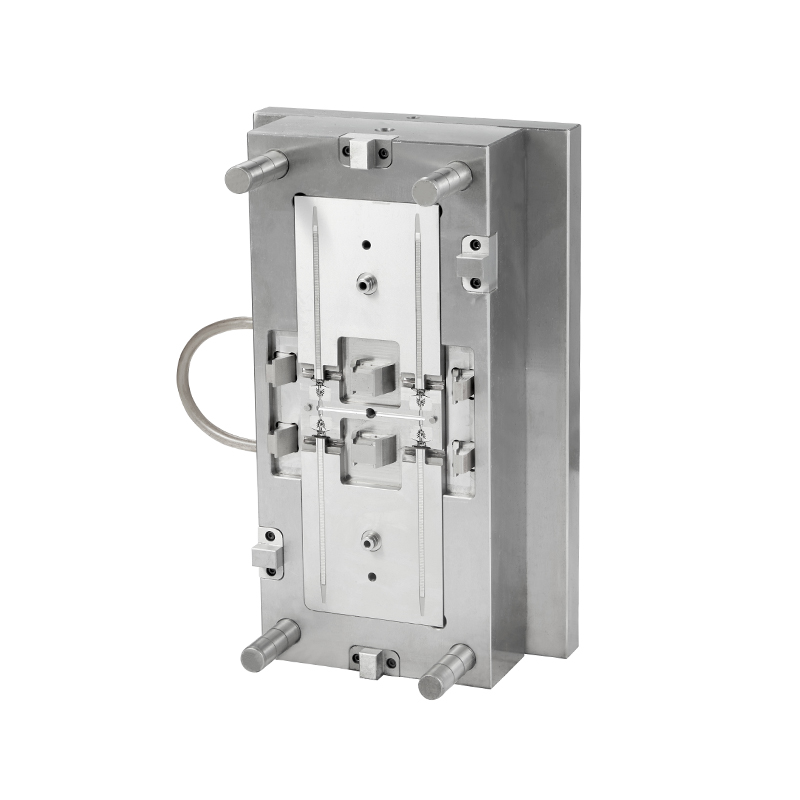
Manufacturing Processes for Precision Mold Components
Producing a precision mold involves multiple subtractive and additive steps, each with defined tolerances.
- High-speed milling (HSM) – Spindle speeds of 15,000–40,000 RPM with carbide or CBN (cubic boron nitride) tools. Feed rates of 2–6 m/min. HSM achieves geometrical tolerances of ±0.005–0.010 mm on cavity surfaces. Step-over distance (distance between tool paths) is set at 0.05–0.15 mm for finishing passes. Surface roughness after HSM is Ra 0.2–0.4 μm, requiring polishing for optical surfaces.
- Electrical discharge machining (EDM) – Used for deep ribs, sharp internal corners (radius below 0.3 mm), and details where tool access is limited. Sinker EDM uses a graphite or copper electrode. Material removal rate is 100–400 mm³/min for roughing and 10–50 mm³/min for finishing. Surface finish after finishing EDM is Ra 0.8–2.0 μm, followed by polishing or stoning. Dimensional accuracy of ±0.005 mm is achievable with multiple finishing passes.
- Wire EDM – Used for punch plates, core pins, and ejection holes. Wire diameter ranges from 0.10 mm to 0.30 mm (brass or coated wire). Cutting accuracy is ±0.002–0.005 mm. Surface finish (Ra 0.2–0.5 μm) requires no further processing for most applications. Maximum workpiece thickness is typically 200–400 mm, depending on machine capacity.
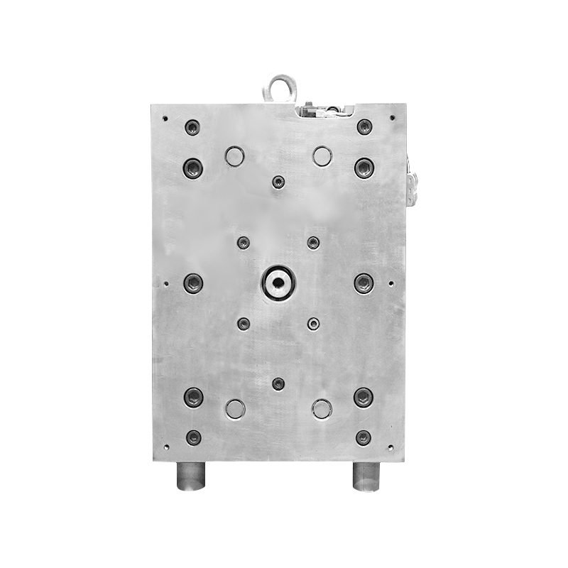
- CNC grinding – For mold bases, guide pins, and bushings. Surface grinders achieve flatness of 0.002 mm per 100 mm length. Cylindrical grinders for core pins achieve roundness within 0.001 mm and diameter tolerance of ±0.002 mm.
Dimensional Tolerances and Quality Control Methods
Precision molds are classified by the achievable dimensional tolerance on the molded part.
Inspection equipment for precision molds:
- CMM (bridge type): Accuracy of ±(1.5 + L/300) μm (L = measured length in mm). Used for cavity geometry, core pin positions, and overall mold dimensions. Measurement time for a 200 mm × 200 mm mold is 30–90 minutes.
- Optical comparator: For 2D profiles of core pins, ejector pins, and small cavity details. Magnification 10× to 100×. Measurement resolution of 0.001 mm for linear dimensions.
- Surface roughness tester: Contact (stylus) type with 2–5 μm tip radius. Measures Ra (arithmetical mean roughness), Rz (average peak-to-valley height), and Rmax. For polished cavities, Ra below 0.05 μm is verified with non-contact (laser confocal) instruments.
- Hardness tester (Rockwell or Leeb): For heat-treated components. Acceptable variation across a mold plate is within ±2 HRC. Hardness below specification indicates inadequate heat treatment, leading to premature wear.
 2026.04.17
 News
News


 English
 中文简体
中文简体 русский