2026.04.24
 News
News
Electrical and Electronic Cable Management
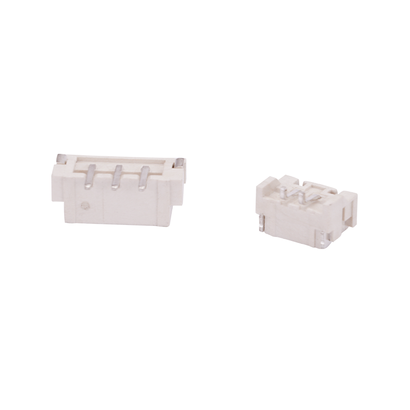
Cable tie molds produce ties used for bundling wires in control panels, data centers, and home entertainment systems. In electrical panel manufacturing, ties of 100 mm to 300 mm length (2.5 mm to 4.8 mm width) secure wires to DIN rails or within cable ducts. For data centers, longer ties (300 mm to 500 mm) with smooth edges are molded to bundle fiber optic cables without damaging the cladding. The molds for these applications include features for rounded edges and consistent head dimensions to ensure uniform locking tension. Typical annual consumption in this sector exceeds 10 billion ties globally.
Automotive and Aerospace Harnessing
Automotive wire harnesses contain 500 to 3,000 individual wires per vehicle. Cable tie molds produce specialized ties with features such as mounting holes (for attaching to car body studs), releasable pawls (for service access), and heat-stabilized materials (up to 125°C under hood). Mold designs for automotive applications include side-action cams to form mounting holes and multi-stage ejection systems to prevent tie deformation. Aerospace applications require ties molded from fluoropolymers (ETFE or PVDF) with flame resistance meeting FAR 25.853. Molds for these materials require corrosion-resistant steel (420 stainless or similar) and polished runner systems to prevent material degradation.
Agriculture, Construction, and Outdoor Uses
Cable tie molds produce UV-stabilized ties (typically black with carbon black content of 2–3%) for outdoor applications. Agricultural ties secure trellises, greenhouse coverings, and irrigation lines. Construction ties bundle rebar (300 mm to 800 mm length) and secure scaffolding safety netting. For these applications, molds incorporate wider gates (1.5 mm to 2.5 mm thickness) to accommodate glass-filled nylon (PA66 GF25 or GF30) which is abrasive to mold surfaces. Cavity surfaces in these molds receive nitriding or chromium plating to extend service life beyond 2 million cycles when molding abrasive materials.
Medical and Food Industry
|
Application |
Tie Material |
Mold Feature |
Output Requirement (ties/hour per cavity) |
Typical Cavity Count |
|
Medical device cable bundling |
PA12 (biocompatible) |
Mirror-polished cavities (Ra 0.05 μm) |
600–800 |
16–32 |
|
Food packaging (sealing bags) |
PA66 or PP (food contact grade) |
Corrosion-resistant steel (316 or 420) |
800–1,200 |
32–64 |
|
Hospital laundry identification |
Nylon 6,6 with color masterbatch |
Multi-color injection (two injection units) |
500–700 |
8–16 |
|
Surgical instrument sterilization wrap |
Heat-stabilized PA46 (150°C autoclave) |
Venting system to avoid gas traps |
400–600 |
8 |
Medical cable tie molds require cleanroom assembly (ISO Class 7 or 8) and validation protocols including dimensional inspection of the locking mechanism (pawl engagement between 0.30 mm and 0.45 mm). Food industry molds avoid external lubricants; instead, self-lubricating guide bushings (graphite-impregnated bronze) are used. The mold surface hardness for medical and food applications is typically 50–54 HRC, with electropolished finishes to prevent bacterial adhesion.
Dimensional Precision and Cavity Arrangement
Locking mechanism tolerances
The functional performance of a cable tie depends on the interaction between the pawl (the angled tooth inside the head) and the rack teeth along the tie body. Cable tie molds maintain specific dimensional ranges: pawl tip radius of 0.10–0.15 mm, pawl angle of 25–35 degrees relative to the insertion direction, and tooth pitch of 1.0–2.5 mm depending on tie size. The clearance between the pawl and the tie body during insertion is held at 0.05–0.10 mm. If this clearance exceeds 0.12 mm, the tie may slip under load; if below 0.03 mm, insertion force becomes too high. Molds achieve these tolerances through wire EDM finishing of the head cavity, followed by coordinate measuring machine (CMM) verification to ±0.005 mm.
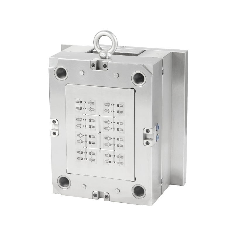
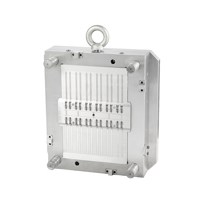
Multi-cavity balance and flow simulation
High-productivity cable tie molds use 32, 48, or 64 cavities arranged in a family or single-type layout. Cavity-to-cavity variation in fill time should remain within 0.05–0.10 seconds. Mold flow analysis software (Moldex3D or Moldflow) is used to design runner systems—typically hot runner with individually heated nozzles or cold runner with balanced H-shaped layouts. A 64-cavity mold for a 150 mm × 3.6 mm tie may have a runner system weight of 150–250 grams per shot (for cold runner), while a hot runner system reduces runner waste to 10–30 grams. Acceptable cavity imbalance is below 5% in part weight across all cavities.
Material selection for mold components subjected to abrasive polymers
When molding glass-filled nylons (PA66 GF15, GF25, or GF30), the sliding surfaces of cable tie molds experience accelerated wear. The tie body is ejected through a stripper plate or using ejector pins; the gate area (where molten plastic enters the cavity) is subject to erosion from glass fibers. For these applications, mold manufacturers use:
Cavity inserts made from powder metallurgy steels (e.g., Vancron 40, hardness 58–62 HRC) with fine carbide distribution, providing 2–3 times the wear resistance of conventionally cast H13.
Nitrided core pins (case depth 0.2–0.4 mm, surface hardness 900–1,100 HV) for the head-forming details.
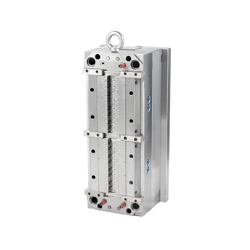
Ejection system design for demolding without deformation
Cable ties have a thin cross-section (1.0–3.0 mm thick) and long length (up to 1,000 mm). Demolding without stretching or bending requires carefully positioned ejectors. Common ejection methods for cable tie molds include:
Stripper plate ejection: A plate that pushes the tie body off the core pins as the mold opens. Suitable for ties longer than 200 mm. Stripper plate stroke is 5–10 mm longer than the tie length.
Recommended Products


 English
 中文简体
中文简体 русский