2026.03.20
 News
News
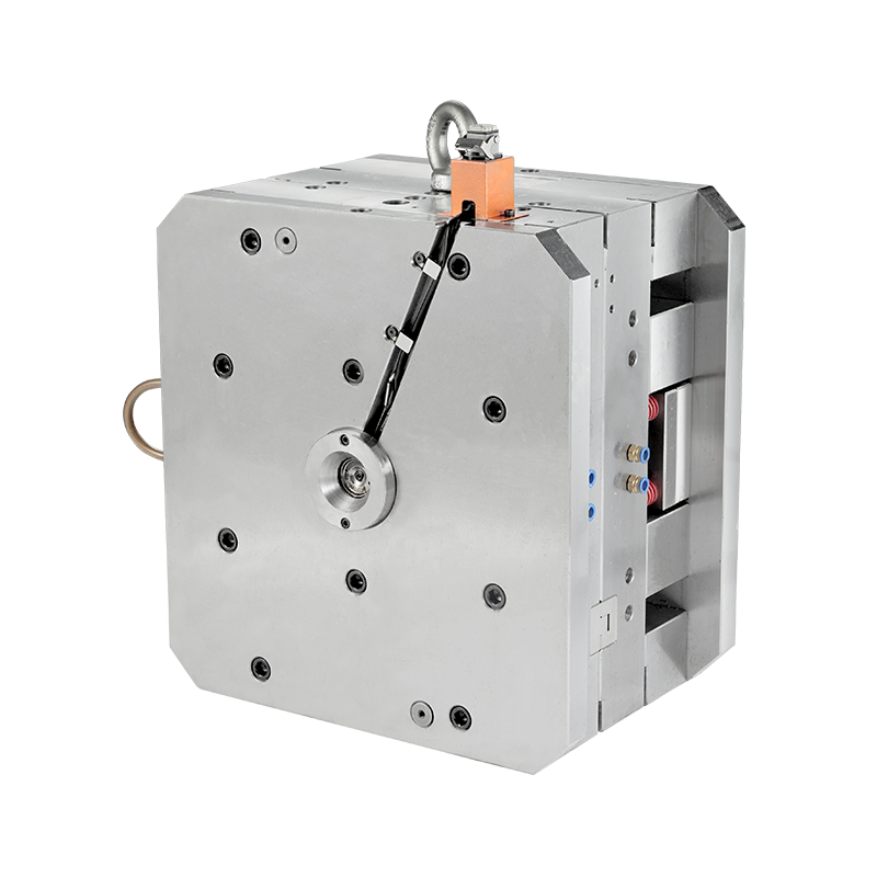
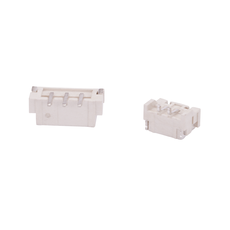
Automotive buckles are functional components used in seat belts, interior trim assemblies, cable fastening systems, and under-hood applications. These buckles are typically produced by injection molding, using engineering plastics such as polyoxymethylene (POM), polyamide (PA), or reinforced polypropylene. The mold used to manufacture these components—commonly referred to as an automotive buckle mold—directly influences dimensional accuracy, structural stability, and production efficiency.
Automotive buckle molds can be categorized according to structural design, molding method, and functional integration. The most common types include:
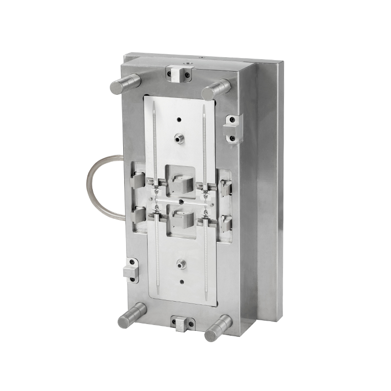
1. Single-Cavity Mold
This mold produces one buckle per cycle and is often used during product development or low-volume production. It allows for easier dimensional adjustment and mold testing.
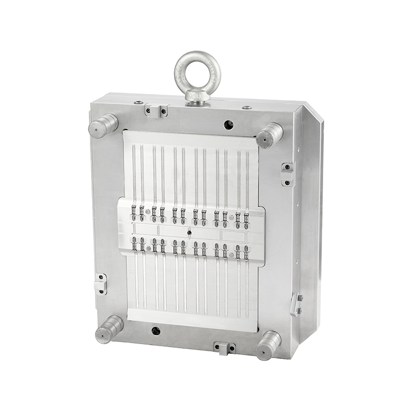
2. Multi-Cavity Mold
Designed for mass production, multi-cavity molds can produce multiple buckles in a single injection cycle. Balanced runner systems are necessary to maintain consistent material flow across all cavities.
3. Two-Plate Mold
A conventional mold structure with a single parting line. It is commonly applied to standard buckle components without complex undercuts.
4. Three-Plate Mold
This mold includes an additional plate to separate the runner from the molded part automatically. It supports higher automation levels and cleaner gate separation.
5. Hot Runner Mold
Equipped with heated manifolds to keep molten plastic flowing directly into cavities, reducing material waste from runners.
6. Insert Mold
Used when metal components, such as springs or reinforcement clips, are embedded into the plastic buckle during molding.
Each type is selected based on production scale, structural complexity, and required mechanical performance.
The development of automotive buckle molds has progressed in response to vehicle safety requirements, lightweight design strategies, and automation trends. The following table outlines key changes over time:
|
Development Aspect |
Earlier Approach |
Current Direction |
|
Material Use |
Standard engineering plastics |
Fiber-reinforced and high-impact polymers |
|
Mold Cavities |
Mostly single or low cavity |
High-cavity molds for mass production |
|
Runner System |
Predominantly cold runner |
Increased use of hot runner systems |
|
Precision Level |
Conventional machining |
CNC and EDM high-precision machining |
|
Automation |
Manual part removal |
Robotic demolding and integrated systems |
|
Simulation |
Limited mold flow analysis |
Widespread use of CAE simulation tools |
Earlier molds were relatively simple in structure, focusing on basic dimensional accuracy. As automotive interior systems became more complex, buckle designs incorporated snap-fit features, flexible hinges, and integrated locking mechanisms. These changes required tighter tolerances and improved cavity surface finishing.
Mold flow simulation software now helps engineers predict shrinkage, weld lines, and air traps before manufacturing begins. This reduces trial-and-error adjustments during mold testing.
Environmental considerations have influenced mold development. Manufacturers increasingly optimize cooling channel layouts to reduce cycle time and energy consumption. These changes reflect broader shifts in automotive manufacturing efficiency and regulatory compliance.
Automotive buckle molds can present technical and operational challenges if not properly designed or maintained. The following numbered analysis outlines common issues:
Dimensional Deviation
Improper shrinkage compensation or uneven cooling can result in dimensional inaccuracies. Buckle components often require precise alignment with mating parts, and deviations may affect assembly performance.
Warpage and Internal Stress
Uneven material flow or inconsistent cooling rates may introduce residual stress within the molded part. Over time, this can lead to deformation, especially in buckles exposed to temperature fluctuations inside vehicle cabins.
Flash Formation
Worn parting lines or insufficient clamping force during injection may produce flash along edges. Flash removal increases post-processing time and may affect appearance or functionality.
Gate Mark and Surface Defects
Improper gate placement can create visible marks or weld lines on the buckle surface. For interior automotive parts, surface consistency is an important quality parameter.
Ejection Deformation
If the ejector system is not properly aligned, thin buckle arms or snap-fit structures may deform during demolding. This risk increases with complex geometries.
Mold Wear and Maintenance Issues
High-volume production can lead to cavity wear, particularly when reinforced plastics are used. Without regular maintenance, wear may affect dimensional consistency and locking precision.
Assembly Misfit
If the mold fails to maintain consistent tolerances, buckle components may not fit correctly with springs, straps, or adjacent interior panels.
These problems can often be mitigated through balanced runner design, optimized cooling systems, regular mold inspection, and precise machining.
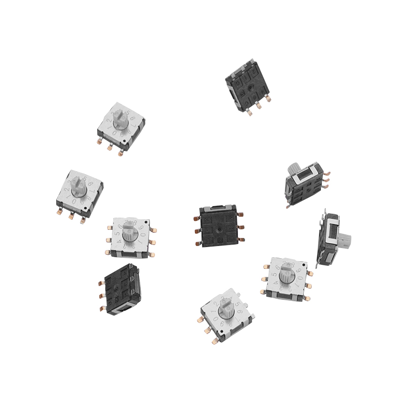
Recommended Products


 English
 中文简体
中文简体 русский