2026.07.24
 News
News
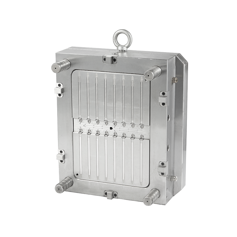
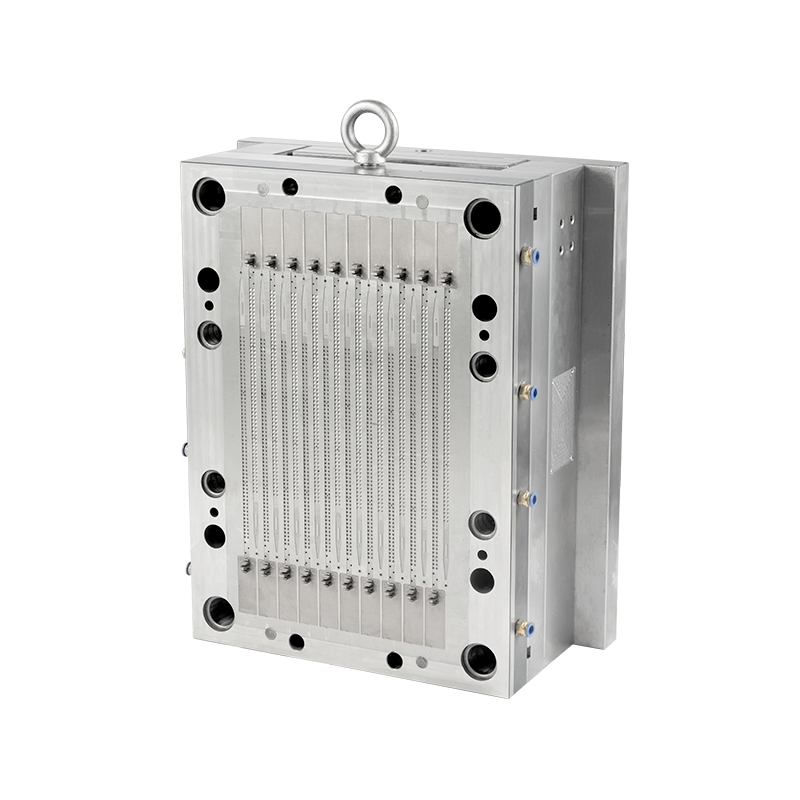
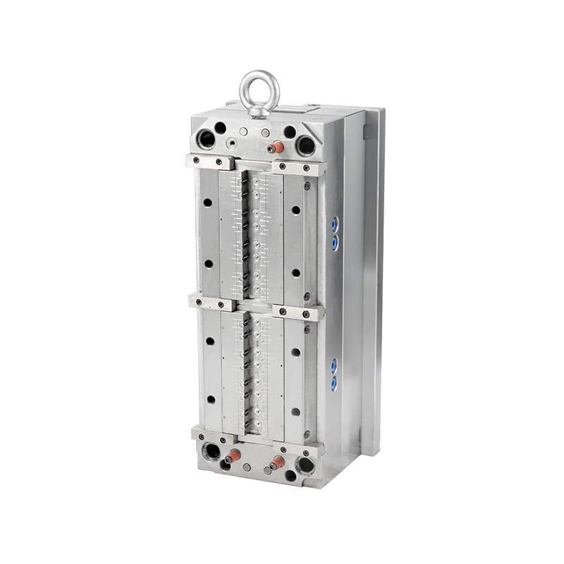
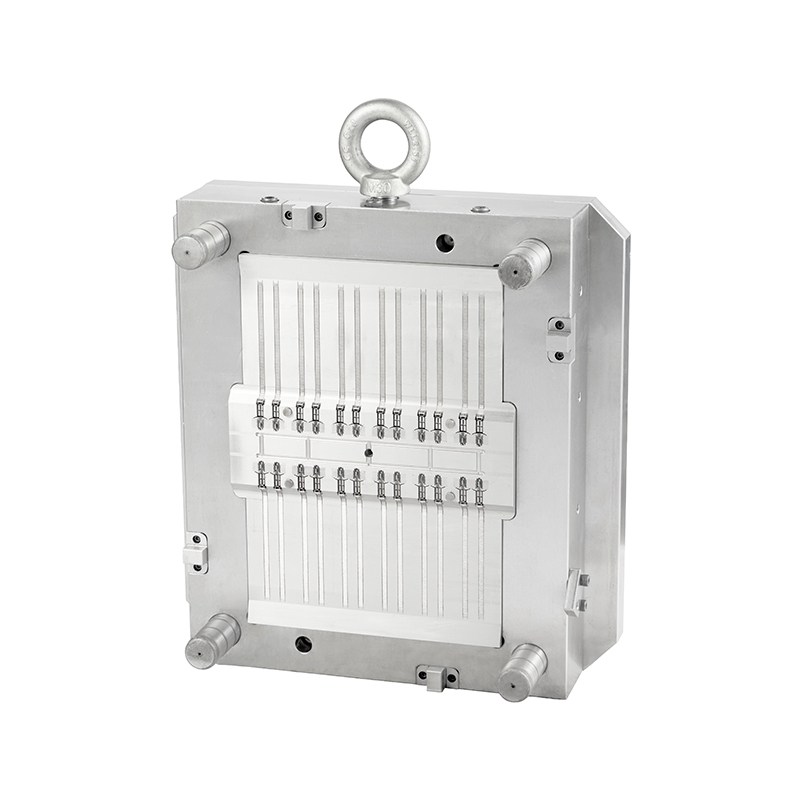
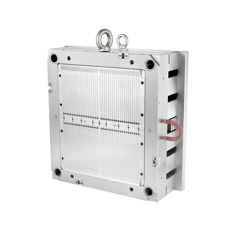
Precision is the foundation of automotive electrical connector production. Connector pins must maintain accurate positions because even a small dimensional deviation can affect terminal insertion, electrical contact reliability, and final assembly performance. A slight offset inside an Automotive Connector Mold may not create an obvious appearance issue, yet it can cause connection failures during vehicle operation.
Pin misalignment usually develops from a combination of tooling accuracy, insert positioning, thermal changes, and molding process conditions. Automotive connectors often require extremely tight dimensional control because terminals, cavities, and plastic housings must work together within limited tolerance ranges. Precision insert molds rely on accurate positioning systems to maintain pin locations throughout production cycles.
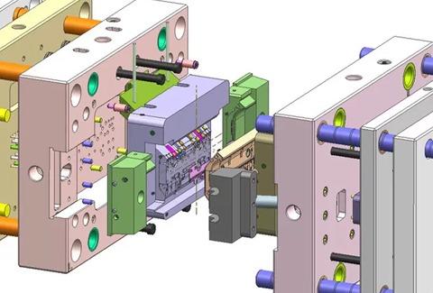
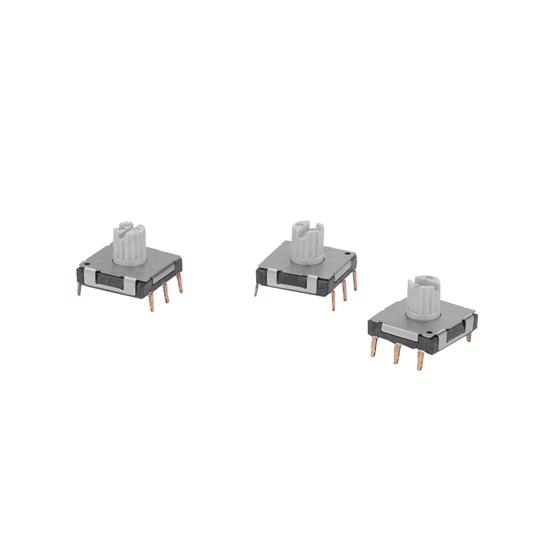
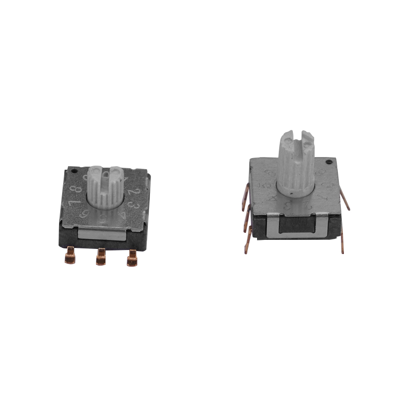
Automotive connectors contain multiple metal terminals arranged inside plastic housings. These terminals must maintain specific spacing, parallelism, and height positions to ensure proper mating with corresponding components.
Unlike general plastic parts, connector products combine metal inserts with polymer molding. The interaction between rigid metal pins and shrinking plastic creates additional dimensional challenges.
A connector mold must therefore control both plastic cavity accuracy and metal insert positioning throughout the molding process.
The placement of metal terminals inside an Automotive Connector Mold is one of the key factors affecting pin alignment. Insert components require accurate positioning before injection begins.
Any movement during mold closing or injection pressure exposure can shift the insert slightly. Although the movement may only measure a few hundred microns, the final connector may fail dimensional inspection.
Precision mold alignment systems commonly use guide pins, bushings, and locating structures to maintain accurate core and cavity positioning. Wear or poor alignment between these components may gradually reduce accuracy.
During injection molding, molten plastic enters the cavity under high pressure. This force does not only fill the cavity; it also applies stress to embedded metal inserts.
Thin terminals or long pin structures are especially sensitive because they have limited resistance against lateral pressure. Without proper support, the flowing resin can create small deflections.
| Cause | Effect on Pin Position |
| High injection pressure | Possible insert movement or deformation |
| Uneven melt flow | Different forces applied around pins |
| Improper fixing structure | Reduced insert stability |
| Tool wear | Gradual positioning deviation |
Temperature variation is another hidden factor behind connector pin displacement. During molding, both steel mold components and metal terminals experience thermal expansion.
Different materials expand and contract at different rates. A metal terminal inside a plastic component may experience stress from surrounding polymer shrinkage during cooling.
These effects may create gradual dimensional changes rather than immediate visible defects. This explains why some connector problems appear during later assembly testing instead of directly after molding.
Long-term production cycles place continuous mechanical stress on mold components. Guide pins, bushings, insert positioning areas, and cavity surfaces may experience gradual wear.
As alignment components lose precision, the relative position between core and cavity sections may change. Even minor mold mismatch can influence connector fit, sealing areas, and assembly clearance.
Plastic shrinkage after cooling can pull surrounding structures in different directions. Connector housings made from materials such as PA, PBT, or reinforced engineering plastics may experience different shrinkage behavior.
The plastic body contracts around metal inserts, creating forces that may slightly change pin orientation.
| Material Factor | Possible Influence |
| Shrinkage rate | Changes final pin position relative to housing |
| Glass fiber content | Creates directional shrinkage behavior |
| Moisture absorption | Affects dimensional stability |
| Cooling speed | Influences internal stress distribution |
Controlling pin accuracy requires cooperation between mold design, insert preparation, and molding process management.
Advanced mold manufacturing methods combine precision machining, inspection equipment, and simulation technology to maintain stable connector dimensions during repeated production cycles.
Pin misalignment in an Automotive Connector Mold is usually caused by multiple small factors working together. Insert movement, injection pressure, thermal stress, material shrinkage, and mold wear can all influence final pin positioning.
Because automotive connectors require reliable electrical and mechanical performance, controlling these hidden variables is essential. Accurate insert positioning, stable tooling structure, and consistent molding conditions help maintain connector quality throughout high-volume production.
Recommended Products



 English
 中文简体
中文简体 русский